
Thermal Fluxes are present everywhere. They are the way in which heat is transferred from one body to another via contact, convection or radiation.
Mathematically, Thermal Fluxes are the derivatives of temperature "T" over time "t". This means that you are able to know the the Thermal Fluxes, you are therefore able to predict temperature evolution of a defined medium.
OUR development KIT "TP AlPHA" -Aims TO
1. Help you integrate into your product an efficient way to measure Thermal Flux that is:
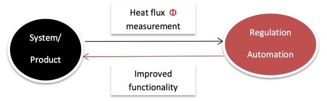
3.Allow the development of new or improved functionality for regulation and automation based on the heat flux information.
- Reliable
- Fast
- Precise
- Non-invasive
3.Allow the development of new or improved functionality for regulation and automation based on the heat flux information.
PROCESS INTEGRATION OF THE HEAT FLUX TECHNOLOGY
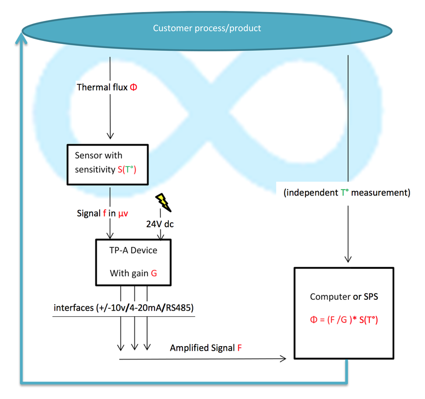
Our system is composed of one of gSKIN®heat flux sensors which measures heat flux and conveys the measured value to our TP-ALPHA device. The TP-A device then converts the signal into a standard signal for any industrial or home computer system.
Therefore, our TP-A device has three standard output interfaces: +/- 10V, 4-20 mA and RS485.
The signal is sent to the computer SPS-system where it can be used as an input to real time thermal flux calculation and further uses.
A full regulation system can be composed of several heat flux sensors sets in parallel.
|
Sensor
The sensor is composed of a sensor head to measure heat fluxes, a cable to transfer measured data, and a standing plug. Upon request, customer-specific sensor configurations are available ( without cable, with different head geometry of material or specific plug). Device TP-A Composed of anIP 57 box, a sensor plug and DC input + output plug. The device runs on a current input of 100mA, 24 V DC (+/-10%). The Device Contains the signal filtering and amplifying system. Each TP-A device has a Specific measured amplification value which must be calibrated annually. DC Input + Output Plug TP-A device plug for DC input and output of amplified signal. DC in / 24V Input current to the TP-A device is a separate 24 VDC +/-10%, 100mA *Also pictured RS485 +/-10V 4-20mA |
Interfaces with Computer or SPS
We can provide computer or SPS interface delivering the amplified output current value of the sensor. Interface possibilities are RS485, +/-10 V (or 0-10 V), 4-20 mA. Interfaces technical specifications are included in document B6-spec interfaces. |
Support Programming
We provide two daily usable exe programs, to have an easy visualisation of the thermal flux for testing purposes.
The Labview VI.exe provides a measured value corrected for T° impact, while out Wintest Program (C++) provides a real time value for the thermal flux or μV values or Isb values.
Wintest Program
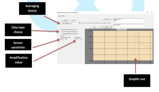
Wintest is a C++ based interface, it includes an automatic TP-A device detection and configuration tool for CPU communication.
Wintest interface allows:
We provide two daily usable exe programs, to have an easy visualisation of the thermal flux for testing purposes.
The Labview VI.exe provides a measured value corrected for T° impact, while out Wintest Program (C++) provides a real time value for the thermal flux or μV values or Isb values.
Wintest Program
Wintest is a C++ based interface, it includes an automatic TP-A device detection and configuration tool for CPU communication.
Wintest interface allows:
- Selecting the amount of data points on which the output values are calculated (1 to 128)
- Selecting between three types of outputs: brut data ADC in Isb, Brut data in μV and converted value in W/m2
- In order to calculate the converted value in W/m2, the sensor sensitivity an amplification value have to be input in the system.
Our Customers can improve their processes or products WITH THERmAL FLUX measurements
|
Examples Include (but not limited to):
|
|
Calculating the thermal Flux
Φ = Thermal FLUX
F = output Value from the TP-A device
G= Gain of TP-A device
So= Sensitivity of Sensor @ 20°c in μV/(W/m2)]
Sc= Sensitivity variation of sensor per °C in μV/(W/m2)/C°] T°= actual measured Temperature in °C
Heat flux calculation Formula
Φ = {(F/G) * [So+Sc*(20-T°)]}
CONTACT US FOR MORE INFORMATION AT MAILTO:INFO@THERMALPLUG.BE